Projects > Astrohub

Over the past few years my focus in astronomy has shifted more towards deep sky imaging. This entails collecting exposures of up to 20 minutes which is only possible by autoguiding. In order to autoguide it is necessary to make use of a guidescope and guide camera. Unfortunately this means additional cables are required, both to provide power and data connectivity. With my portable setup it currently takes about 2 hours to reach the stage where I can begin imaging, and a further 1 hour to tear everything down. In an attempt to decrease setup times and to reduce the tangle of cables I decided to construct what I call an Astrohub. Admittedly, a permanent setup is the preferred solution to the setup/teardown times and that is something I am also working on.
All of my equipment uses a 12V power supply so I needed to ensure I had several 12V connectors built into my solution. I'm not a fan of 12V cigarette lighters as I find them unreliable in the field. It is all too easy to accidentally disconnect them. My preference would have been to use banana plug connectors as these are more secure. However, much of my equipment is fused within the 12V 'cigarette style' connector. I did start looking at building the fuses into my solution, but this simply added complexity where I would no doubt later regret it. For example, I would need different fuses for each piece of equipment and I would need to make sure I always connected the equipment to the same socket. With this in mind I chose to stick with the 12V cigarette style sockets.
While on the subject of power, I should mention that the Gemini unit on my Losmandy GM8 is much happier running at 13.8V. My power supply provides 13.8V, but running these voltages over cable results in a significant amount of voltage drop. I had decided that cable lengths of 5m would be sufficient for my purposes so to reduce voltage drop I chose to use 8mm cable as this is fairly thick. I currently need two 12V power sources, so I built 3 sockets into my design to give me room for expansion in the future. I wired these in parallel because in serial I would need all 3 devices connected to complete the circuit. I included a power switch in the circuit to provide me with an easy way to remove power to all my equipment if I'm next to the telescope. This was perhaps my biggest mistake. It was the only component I hadn't given much thought to in advance and while standing in Maplins looking at the alternatives I chose a red illuminated rocker switch. When I reached the testing stage it was obvious that I should not have chosen an illuminated switch as it lit up the whole room! I quickly replaced the switch with a non-illuminated version once I realised.
While on the subject of power, I should mention that the Gemini unit on my Losmandy GM8 is much happier running at 13.8V. My power supply provides 13.8V, but running these voltages over cable results in a significant amount of voltage drop. I had decided that cable lengths of 5m would be sufficient for my purposes so to reduce voltage drop I chose to use 8mm cable as this is fairly thick. I currently need two 12V power sources, so I built 3 sockets into my design to give me room for expansion in the future. I wired these in parallel because in serial I would need all 3 devices connected to complete the circuit. I included a power switch in the circuit to provide me with an easy way to remove power to all my equipment if I'm next to the telescope. This was perhaps my biggest mistake. It was the only component I hadn't given much thought to in advance and while standing in Maplins looking at the alternatives I chose a red illuminated rocker switch. When I reached the testing stage it was obvious that I should not have chosen an illuminated switch as it lit up the whole room! I quickly replaced the switch with a non-illuminated version once I realised.
Most of my equipment requires USB connectivity, but my Gemini controller uses a serial connector. My laptop doesn't have a serial port so the obvious solution is to use a USB to serial converter. I planned to build the converter into my solution, but as the Gemini controller is very sensitive to ground loops and static discharge I decided I would also incorporate some form of isolation. I had already decided to use 5m USB2 capable cables so I started searching for a device that would isolate between the USB cable and the serial converter.
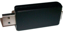
I found several products that would do the trick, but many were either too large or too expensive. Finally I came across the USB2ISO device produced by a company in Denmark. At about 35 euros it was the best option I had found so I ordered one. After testing it thoroughly I'm happy to say it does exactly what I intended. It completely isolates the connection between the laptop and the device connected to the serial port.
I decided I would add 2 serial connectors, each provided by a USB to serial converter. As for USB ports, I chose to build 3 of these into the solution. Each would be connected by a separate 5m USB2 extender. So, that meant I needed a total of five 5m USB2 cable extenders. You might ask why I did it this way instead of using a USB hub. The reason I did this is because the USB specification means that a single port can carry a maximum of 500mA. If I use a standard USB hub this is then shared between each device. Admittedly I could have used a powered hub, but most run off 240V rather than 12V. I could have found a 12V powered hub, but I preferred to keep as much power as possible for the Gemini. That wasn't the only reason I didn't want to use a hub. Five separate USB2 cables increase the available bandwidth and I have the option of connecting to two separate laptops if desired. Finally, 3 USB ports may not be sufficient in the future so I may end up attaching a hub to one of them in the future anyway. I'd prefer not to have to chain hubs together as that can cause connectivity issues.
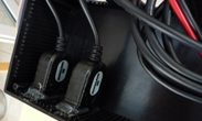
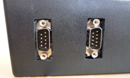
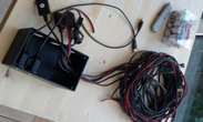
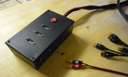
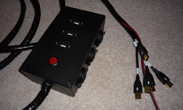
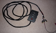
All of this needed to fit inside a Maplin 17cm x 12xm x 5cm project box. To make the construction process easier I added USB sockets which I placed within the lid of the project box and connected to the USB extender cables. This made for quite a professional finish when fitted next to the power switch. Fitting the serial ports was not so easy as they were designed as standalone devices. I resorted to using epoxy resin to bond them to the project box. Fitting everything inside the project box was quite a challenge! You'll notice from the images that I am using banana plugs on the end of the power cable to connect to my 13.8V power supply.
Once I successfully tested everything was working I used cable wrap to make the finished product a little more professional, and to help reduce the likelihood of cables getting tangled or damaged in operation. The total cost of all parts was somewhere between £100 and £150. Quite expensive perhaps for what it is, but I enjoyed making it and it does what I intended so I'm happy!
